Sangaku DIY NuTube Headphone Amp / Preamp
Sep 1, 2022 at 11:32 PM Post #107 of 144
Hey so I have an issue and I've been putting this off for awhile. The front panel of the sangaku DIY case does not fit, the gain switch is situated slightly above the hole of front panel and I have been trying to re position the switch with no avail. I am the second owner of this amp and the solder used probably had no resin as desoldering is near impossible with what I currently have (desolder pump). Need some suggestions on how I can approach this or if I can commission one of you guys to help fit this in the case.
 
Sep 1, 2022 at 11:36 PM Post #108 of 144
Hey so I have an issue and I've been putting this off for awhile. The front panel of the sangaku DIY case does not fit, the gain switch is situated slightly above the hole of front panel and I have been trying to re position the switch with no avail. I am the second owner of this amp and the solder used probably had no resin as desoldering is near impossible with what I currently have (desolder pump). Need some suggestions on how I can approach this or if I can commission one of you guys to help fit this in the case.

ChipQuik and desoldering braid are your part removing and reseating friends.
 
Sep 1, 2022 at 11:45 PM Post #109 of 144
ChipQuik and desoldering braid are your part removing and reseating friends.
Maybe but the pins on the gain switch are all bent, I have gotten most of the solder with the pump but have not been able to get it all with some solder left under the bent pin. I have nothing that can bend the pin back upright since the pins are rather thick and don't want to burn myself in the process.

I am completely fine with commissioning someone to do this as I have school starting next week so don't want to spend a lot more time on this. In Canada so preferably domestic but US is fine too
 
Sep 1, 2022 at 11:57 PM Post #110 of 144
Maybe but the pins on the gain switch are all bent, I have gotten most of the solder with the pump but have not been able to get it all with some solder left under the bent pin. I have nothing that can bend the pin back upright since the pins are rather thick and don't want to burn myself in the process.

I am completely fine with commissioning someone to do this as I have school starting next week so don't want to spend a lot more time on this. In Canada so preferably domestic but US is fine too

You don't need to remove all the solder. ChipQuik has a really low melting point, so you actually add that as *more* solder. Then you heat all the joints to melt them, it stays liquid for a really long time, and you can move/remove the part. Then clean up the ChipQuik with desolder braid, and add fresh proper solder.
 
Last edited:
Sep 2, 2022 at 12:11 AM Post #111 of 144
You don't need to remove all the solder. ChipQuik has a really low melting point, so you actually add that as *more* solder. Then you heat all the joints to melt them, it stays liquid for a really long time, and you can move/remove the part. Then clean up the ChipQuik with desolder braid.
Hmmm maybe but need to realign pins and I could not find anything strong and thin enough to get under the pin. Tries using with my precision flatheat scrwdriver but it was either solder stick stickint the pin down to the pcb or just not enough strength to realign the pin
 
Sep 2, 2022 at 12:12 PM Post #112 of 144
Hey so I have an issue and I've been putting this off for awhile. The front panel of the sangaku DIY case does not fit, the gain switch is situated slightly above the hole of front panel and I have been trying to re position the switch with no avail. I am the second owner of this amp and the solder used probably had no resin as desoldering is near impossible with what I currently have (desolder pump). Need some suggestions on how I can approach this or if I can commission one of you guys to help fit this in the case.
Could you maybe attach a picture? If you don’t have chipquick, you could add solder to the heated legs to loosen and clean the older solder

If you need to realign the pins, it would probably be easiest to remove the entire switch from the board first. Not necessary usually, but if you’re having trouble it might help. One of my switches was just slightly skewed left at first - I heated the solder and pads, moved it slightly to fix the issue
 
Sep 2, 2022 at 2:28 PM Post #113 of 144
Could you maybe attach a picture? If you don’t have chipquick, you could add solder to the heated legs to loosen and clean the older solder

If you need to realign the pins, it would probably be easiest to remove the entire switch from the board first. Not necessary usually, but if you’re having trouble it might help. One of my switches was just slightly skewed left at first - I heated the solder and pads, moved it slightly to fix the issue
Yeah I can provide pictures soon, I do think I need to realign pins first though to remove the component since the pins are so tightly bent down to the pcb. Also I can't heat pins and move switch down since switch gets really hot otherwise
 
Sep 2, 2022 at 4:06 PM Post #114 of 144
Yeah I can provide pictures soon, I do think I need to realign pins first though to remove the component since the pins are so tightly bent down to the pcb. Also I can't heat pins and move switch down since switch gets really hot otherwise
The switch getting hot shouldn’t really be an issue. It’s designed to be soldered - if you do it quicker than 5min real time I’m sure it’s fine
 
Sep 2, 2022 at 4:07 PM Post #115 of 144
Yeah I can provide pictures soon, I do think I need to realign pins first though to remove the component since the pins are so tightly bent down to the pcb. Also I can't heat pins and move switch down since switch gets really hot otherwise
Solder pump and solder wick are both good at removing solder. I use both depending on the task
 
Oct 11, 2022 at 2:35 AM Post #116 of 144
Hey so I came across an issue for my sangaku DIY amp. There's static coming from the right side from the amp itself. Checked with the cables and headphones, and they were all good. What I found out is that in low volumes, the static is very minimal and unnoticeable but at medium volumes, its noticeable and only on the right side. When I crank the volume knob all the way to the max. one of the nutubes turn off. Wondering what the issue is so I can just quickly fix it rather than trial and error and waste a few hours on it.

Thanks

Edit

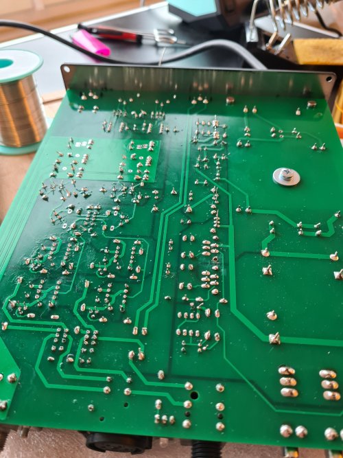
I looked at the solder joints in which the nutube was connected with. Solder joints seem fine, maybe the pcb solder joints? Seems like theres corrosion. Also lots of crackling with static as well. This what it sounds like
 

Attachments

  • 20221011_023135.jpg
    20221011_023135.jpg
    375.1 KB · Views: 0
  • 20221011_023144.jpg
    20221011_023144.jpg
    365.4 KB · Views: 0
  • 20221011_151310.jpg
    20221011_151310.jpg
    634 KB · Views: 0
  • 20221011_151733.jpg
    20221011_151733.jpg
    442.2 KB · Views: 0
  • 20221011_151344.jpg
    20221011_151344.jpg
    819.6 KB · Views: 0
Last edited:
Oct 12, 2022 at 5:26 PM Post #118 of 144
You may want to check resistance from the nutube pins to your solder joints on the PCB, you might need to potentially reflow a joint, or perhaps the ribbon has shorted internally, they are pretty delicate.
ok, multimeter would do the job for checking resistance? I think my friend might have one or I can get it off amazon. If ribbon shorted, replace with new one?
 
Oct 12, 2022 at 5:44 PM Post #119 of 144
Yes exactly. If you're doing work like this I'd recommend investing in one. Flukes are well respected if you can spare the $$. If any of the connections are showing more than 0.1 or 0.2 ohms they may be the culprit.

If the ribbon shorted, I'd personally just replace wherever it did with a wire or wires. Something like 24 gauge should suffice, stranded as solid wire would transfer more vibration to the Nutube platform from the PCB.
 

Users who are viewing this thread

Back
Top